- 您现在的位置:买卖IC网 > Sheet目录1221 > IRADK10 (International Rectifier)KIT DESIGN 3-PH 115-230ACV MOTOR
�� �
�
�IRADK10�
�Cycle� control� description�
�Drive� Status� Feedback�
�The� “DRIVE� STATUS”� display� is� the� field� where� the� GUI� in-�
�dicates� what� caused� the� drive� to� shut� down� protecting� the�
�power� module.� The� micro� controller� will� shut� down� the� sys-�
�tem� if� one� of� the� following� faults� occurs:�
�?�
�?�
�?�
�Short Circuit� :� is� shown� when� a� short� circuit� is� ap-�
�plied� from� phase� to� phase� at� the� output� connec-�
�tions.�
�Over Voltage� :� is� shown� when� the� DC� bus� voltage�
�exceeds� 400V.� Note� The� bus� voltage� can� climb�
�to� a� shut� down� condition� if� the� deceleration� set-�
�ting� is� set� too� high.�
�Under voltage� :� When� the� input� AC� voltage� at� the�
�rectifier� is� insufficient� to� provide� a� bus� voltage� of�
�100VDC,� the� system� shuts� down� and� cannot� start�
�the� motor.�
�Figure� 6.� GUI� control� panel� screen�
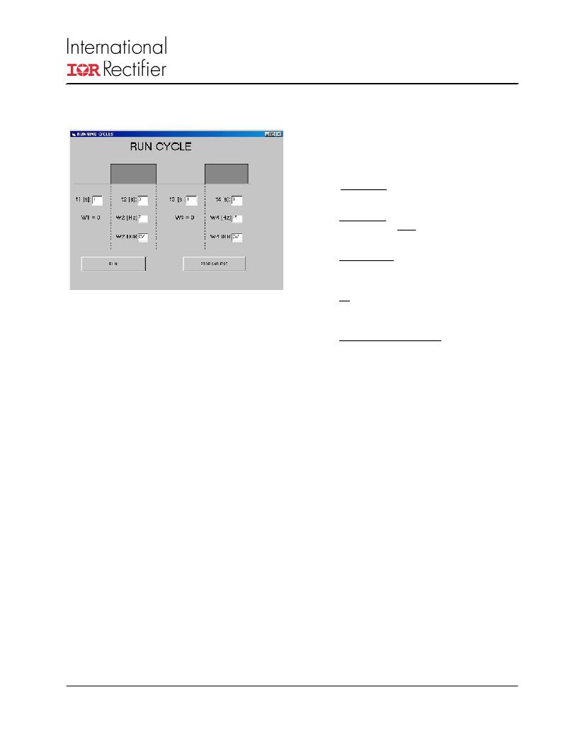
�As� stated� above,� the� “GO� CYCLE”� command� button� of� the�
�GUI� tool� will� bring� you� to� the� next� form,� wherein� the� drive�
�cycle� control� may� be� adjusted,� programmed,� started� and�
�stopped.�
�Observe� 4� time� intervals� (t1,� t2,� t3,� t4)� and� the� frames� where�
�their� duration� may� be� adjusted� by� editing� the� number� writ-�
�ten� in� the� appropriate� fields.� When� adjusting� these� num-�
�bers,� make� sure� you� enter� an� integer� number� of� seconds�
�not� exceeding� 30.�
�For� the� time� intervals� t1� and� t3,� the� assumed� speed� refer-�
�ence� is� zero.� Intervals� t2� and� t4� will� have� non-zero� speeds.�
�Their� speeds� W2� and� W4,� expressed� in� [Hz]� may� be� ad-�
�justed� by� editing� the� fields� indicated� by� W2� [Hz]� and� W4�
�[Hz]� labels.�
�You� must� enter� an� integer� number� between� 0� and� 100.� for�
�both� intervals,� the� direction� of� rotation� is� adjusted� by� writing�
�into� the� CW/CCW� fields.�
�When� a� CW� string� is� found� in� above� fields� (default),� the� CW�
�direction� of� the� motor� shaft� is� commanded.� Otherwise,� for�
�whatever� string� other� than� CW,� the� drive� assumes� a� CCW�
�direction.� The� cycle� begins� by� pressing� the� “RUN”� button.�
�Whenever� the� user� wants� to� stop� the� cycle,� the� STOP� but-�
�ton� has� to� be� pressed.� The� “STOP”� button� will� decelerate�
�the� motor.� During� deceleration� a� “WAIT!!!”� message� will�
�appear� across� the� form,� and� the� GUI� will� revert� to� the� previ-�
�ous� frame� once� the� speed� reaches� zero.� While� the� cycle� is�
�running,� the� user� may� observe� the� DC-link� current� and� the�
�heat� sink� temperature.�
�www.irf.com�
�?�
�?�
�I2T� :� This� is� the� IGBT� SOA� protection.� If� the� output�
�power� exceeds� 400W� for� over� 2� minutes,� the�
�power� inverter� will� shut� down� preventing� the� power�
�module� from� over-heating.�
�Heat sink over temperature� :� If� the� heat� sink� tem-�
�perature� rises� more� than� “Heatsink� temperature”�
�set� by� the� user,� the� system� will� shut� down.�
�7�
�发布紧急采购,3分钟左右您将得到回复。
相关PDF资料
IRADK31
DESIGN KIT 1/4 HP DC FOR IR31XX
IRAUDAMP1
KIT REFERENCE DESIGN W/IR2011S
IRAUDAMP4
KIT 2CH 120W HALF BRDG AUDIO AMP
IRCS2277S
DEMO FOR 3-PHASE/380V MOTOR DRV
IRDC2085S-DF
BOARD EVAL CONV DC BUS W/IRF6603
IRDC3038
KIT W/IRU3038 PWM CTRL DDR 14-PI
IRDC3039
BOARD EVAL CTRLR PWM W/IRU3039
IRDC3046
KIT W/IRU3046 DUAL PWM LDO CTRLR
相关代理商/技术参数
IRADK31
功能描述:电源管理IC开发工具 1/4 HP DC brushless Mtr using IR31xx
RoHS:否 制造商:Maxim Integrated 产品:Evaluation Kits 类型:Battery Management 工具用于评估:MAX17710GB 输入电压: 输出电压:1.8 V
IRADK-S10UP60
制造商:International Rectifier 功能描述:
IRAE410
制造商:MURATA 制造商全称:Murata Manufacturing Co., Ltd. 功能描述:PYROELECTRIC INFRARED SENSORS IRA SERIES
IRA-E410
制造商:MURATA 制造商全称:Murata Manufacturing Co., Ltd. 功能描述:PYROELECTRIC INFRARED SENSORS IRA SERIES
IRA-E410QW1
制造商:Murata Manufacturing Co Ltd 功能描述:PYROELECTRIC INFRARED SENSOR - Bulk
IRA-E410S1
制造商:MURATA 制造商全称:Murata Manufacturing Co., Ltd. 功能描述:PYROELECTRIC INFRARED SENSORS IRA SERIES
IRA-E410ST1
制造商:MURATA 制造商全称:Murata Manufacturing Co., Ltd. 功能描述:PYROELECTRIC INFRARED SENSORS IRA SERIES
IRA-E420
制造商:MURATA 制造商全称:Murata Manufacturing Co., Ltd. 功能描述:Dual Type Pyroelectric Infrared Sensor